how to draw slotted spoon in 3d
Sometimes, y'all need to draw lines, circles or curves in your Unity games. In these cases, you can use Unity's LineRenderer class. In this tutorial, we will see how nosotros can draw lines, polygons, circles, moving ridge functions, Bézier Curves. And also we will run into how nosotros tin can do a free drawing using Line Renderer in Unity3D. In order to meet our other Unity tutorials, click here.
Line Renderer Component
To draw a line nosotros take to add a LineRenderer component to a game object. Even if this component tin can be attached to any game object, I suggest yous create an empty game object and add the LineRenderer to this object.
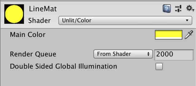
We need a material which volition exist assigned to LineRenderer. To do this create a material for the line in Projection Tab. Unlit/Color shader is suitable for this material.
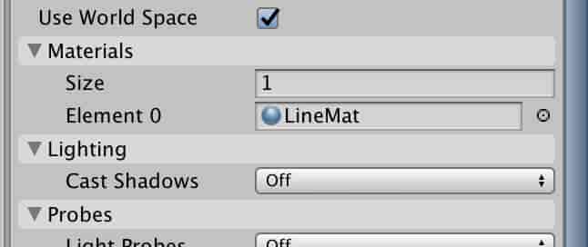
Assign LineMat textile to the Line Renderer component.
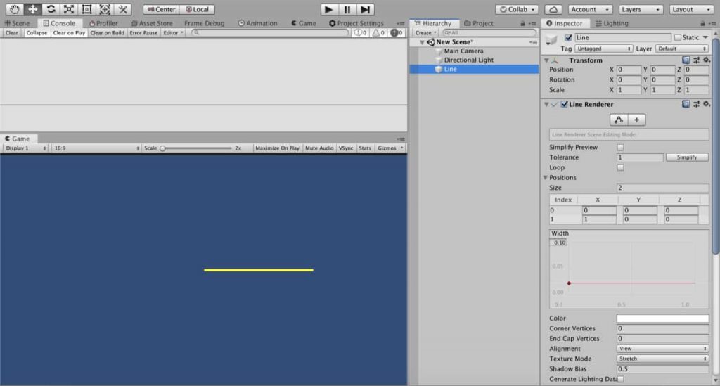
Line Renderer draws lines between adamant positions. In other words, we tell the Line Renderer the points which will be continued and Line Renderer connects these points.
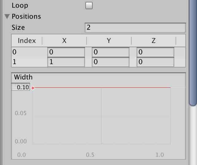
In the Positions section, you tin change the number of points and positions of points. If you enter two unlike points, you will get a direct line. You can as well change the width of the line in the section below.
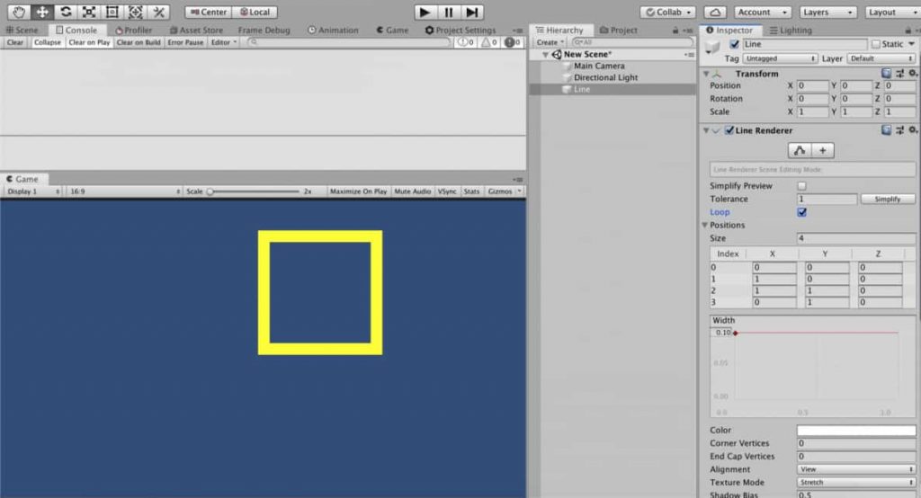
As well, two describe a triangle, you need iii points and to draw a rectangle yous demand iv points. Let'southward depict a rectangle every bit an example.
To draw a rectangle, we need to gear up positions of 4 points. Nosotros likewise take to cheque the Loop toggle to obtain a closed shape.
Drawing Lines From C# Script
If we want to draw or control lines in existent-time, nosotros need to create a C# script. To draw lines from a script, nosotros determine the size of position array and coordinates of positions in C# script. Therefore, LineRenderer can connect the points.
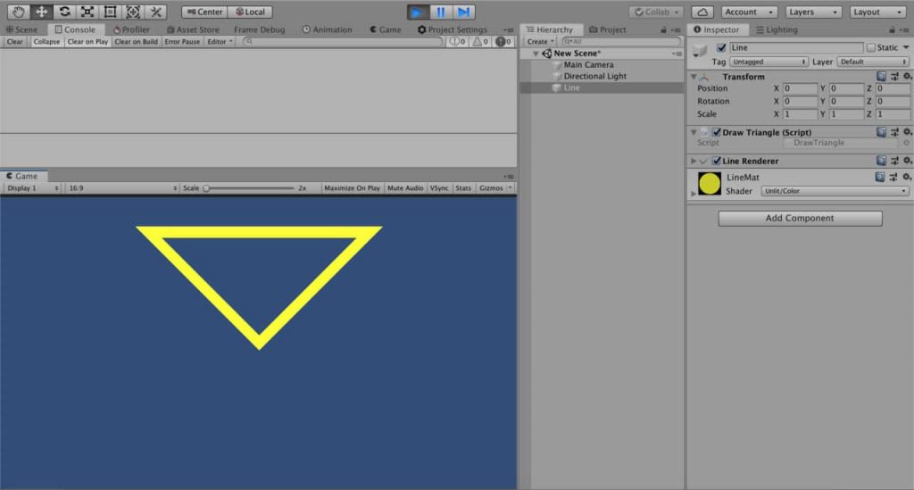
Let's draw a triangle using a script as an example. First, create a script with the proper noun "DrawScript". And attach this script to a game object which already has a LineRenderer component.
public class DrawScript : MonoBehaviour { private LineRenderer lineRenderer; void Offset( ) { lineRenderer = GetComponent<LineRenderer> ( ) ; Vector3[ ] positions = new Vector3[ 3 ] { new Vector3( 0 , 0 , 0 ) , new Vector3( - 1 , 1 , 0 ) , new Vector3( 1 , 1 , 0 ) } ; DrawTriangle(positions) ; } void DrawTriangle(Vector3[ ] vertexPositions) { lineRenderer.positionCount = three ; lineRenderer.SetPositions(vertexPositions) ; } }
This script will draw a triangle. Note that we already set the line width to 0.1 and checked the loop toggle, before. Therefore the same setting is also valid here.
Nosotros can also change the line width from the script using startWidth and endWidth. In improver to this, if you would like to alter line width by position, you can set different values to them. In this instance, Line Renderer will interpolate the line width according to position.
public class DrawScript : MonoBehaviour { individual LineRenderer lineRenderer; void Get-go( ) { lineRenderer = GetComponent<LineRenderer> ( ) ; Vector3[ ] positions = new Vector3[ 3 ] { new Vector3( 0 , 0 , 0 ) , new Vector3( - 1 , 1 , 0 ) , new Vector3( ane , 1 , 0 ) } ; DrawTriangle(positions, 0.02 f , 0.02 f ) ; } void DrawTriangle(Vector3[ ] vertexPositions, float startWidth, float endWidth) { lineRenderer.startWidth = startWidth; lineRenderer.endWidth = endWidth; lineRenderer.loop = true ; lineRenderer.positionCount = iii ; lineRenderer.SetPositions(vertexPositions) ; } }
Drawing Regular Polygons and Circles
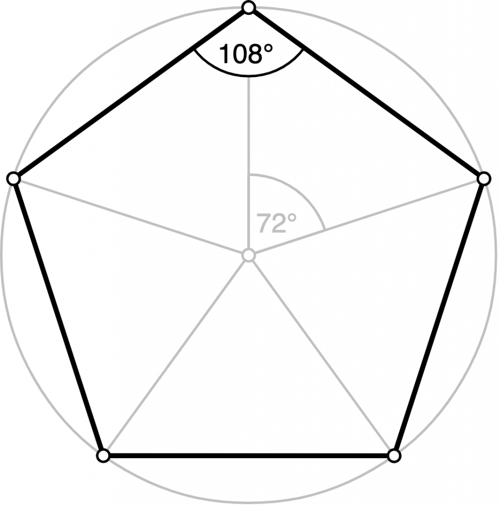
In this section, nosotros are going to see how we can write a method that draws regular polygons. Since circles are n-gons which has big northward, our function will exist useful for circles also. Just beginning, let me explain the mathematics behind it.
Vertices of regular polygons are on a circle. Also, the center of the circle and the center of the polygon are height of each other. The about reliable method to draw a polygon is to observe the bending between successive vertices and locate the vertices on the circumvolve. For instance, angle of the arc between successive vertices of a pentagon is 72 degrees or for an octagon, it is 45 degrees. To find this bending, we can divide 360 degrees(or 2xPI radians) with the number of vertices.
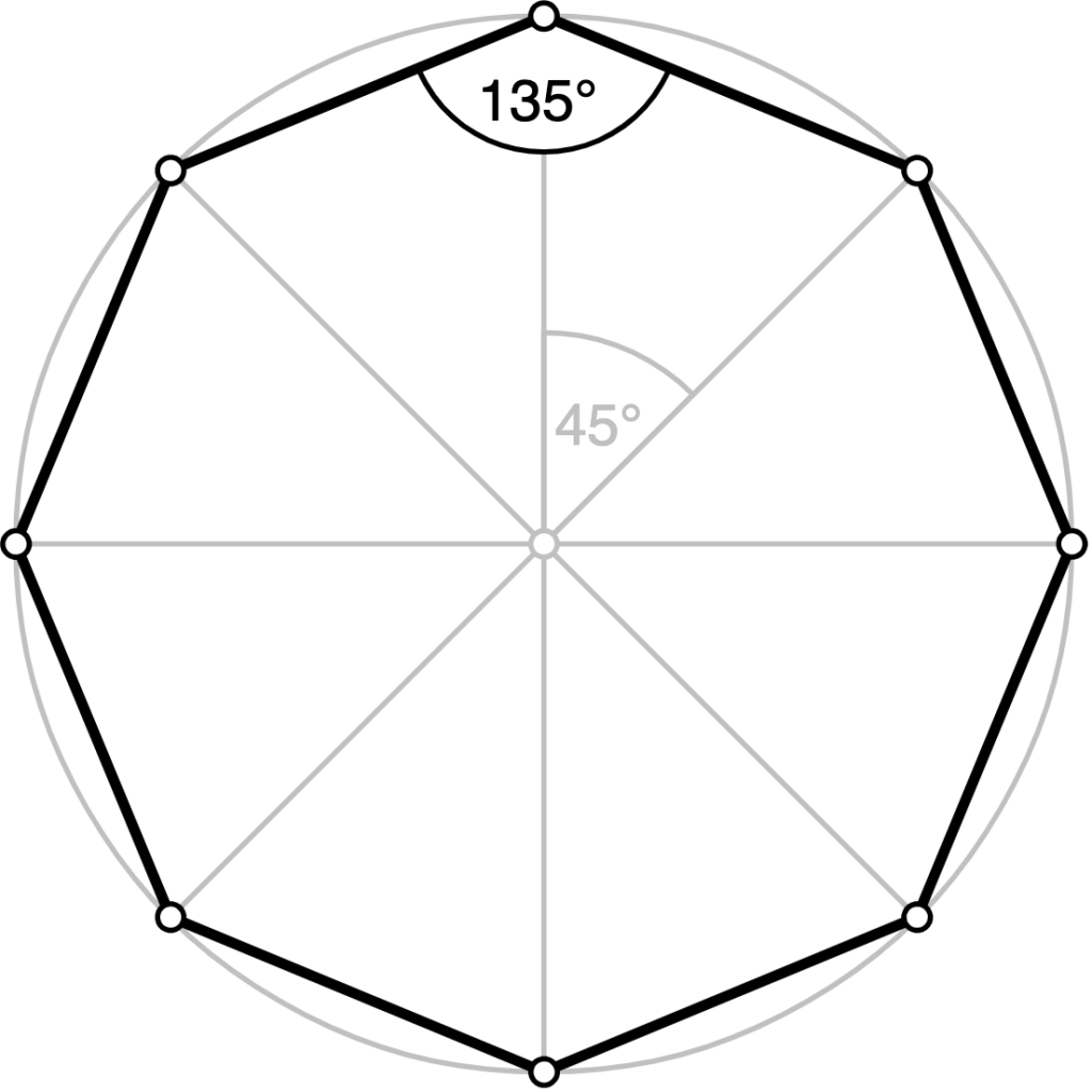
Then we demand to find the positions of the vertices. To do this we assign an initial point for the starting time vertex and rotate this vertex for each vertex using a rotation matrix.
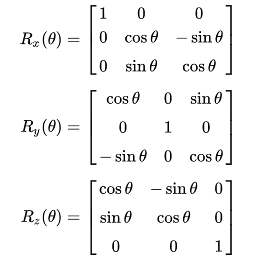
As you probably know, in club to rotate a signal around an centrality, we multiply the position vector of the bespeak with the rotation matrix. Rotation matrices for rotations around x, y and z axes are given on the right.
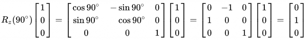
For instance, when nosotros want to rotate a indicate past 90 degrees around the z-axis, which has a coordinate (ane,0,0), nosotros multiply the position vector by a rotation matrix.
Nosotros need to construct a rotation matrix to rotate each vertex around the z-axis. Let'south me write our DrawPolygon method kickoff and explicate information technology.
void DrawPolygon( int vertexNumber, float radius, Vector3 centerPos, float startWidth, float endWidth) { lineRenderer.startWidth = startWidth; lineRenderer.endWidth = endWidth; lineRenderer.loop = true ; float angle = 2 * Mathf.PI / vertexNumber; lineRenderer.positionCount = vertexNumber; for ( int i = 0 ; i < vertexNumber; i+ + ) { Matrix4x4 rotationMatrix = new Matrix4x4( new Vector4(Mathf.Cos(angle * i) , Mathf.Sin(angle * i) , 0 , 0 ) , new Vector4( - 1 * Mathf.Sin(angle * i) , Mathf.Cos(angle * i) , 0 , 0 ) , new Vector4( 0 , 0 , ane , 0 ) , new Vector4( 0 , 0 , 0 , 1 ) ) ; Vector3 initialRelativePosition = new Vector3( 0 , radius, 0 ) ; lineRenderer.SetPosition(i, centerPos + rotationMatrix.MultiplyPoint(initialRelativePosition) ) ; } }
Yous may wonder why the constructed rotation matrix is 4×iv. In reckoner graphics, the three-dimensional world is represented equally 4-dimensional but this topic is not related to our business concern hither. We just use information technology as if it is three-dimensional.
Nosotros set the position of initial vertex and rotate it using rotationMatrix each time and add the center position to information technology.
The post-obit image is an example of a hexagon which is drawn past this method.

If you increment the number of vertex points, this polygon turns to a circle.

Drawing Waves
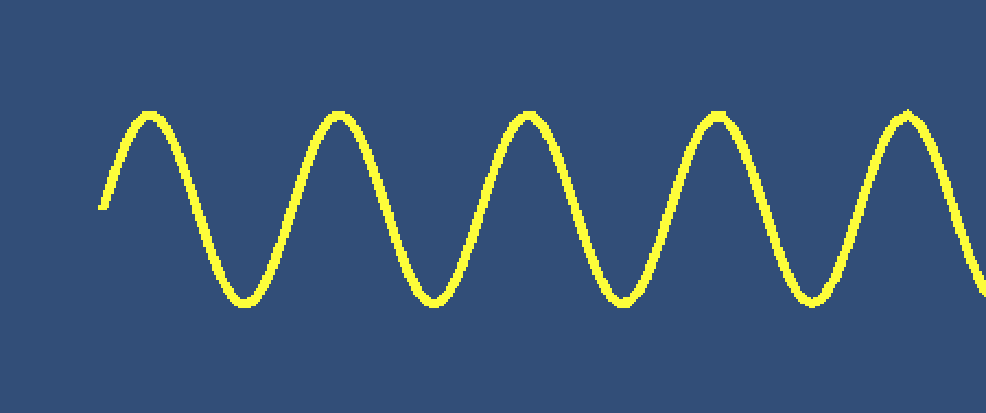
In this section, we are going to draw a sinusoidal moving ridge, a traveling moving ridge and a standing wave using sine function.
The mathematical part of the sine wave is given by the following:
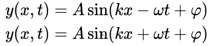
where
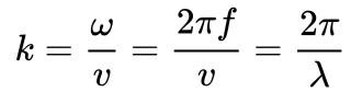
Here, k is wave number, f is frequency, ω is the athwart frequency, λ is wavelength, 5 is the linear speed, t is the time and φ is the phase angle. We will not worry about the phase angle in our discussions.
Sine wave equation with a minus sign represents traveling moving ridge from left to correct and the equation with plus sign represents a traveling line moving ridge correct to left.
In club to draw a stable sinusoidal wave, we tin drop the time part. The following method will describe a sine wave.
void DrawSineWave(Vector3 startPoint, bladder aamplitude, bladder wavelength) { float ten = 0f; float y; float thou = two * Mathf.PI / wavelength; lineRenderer.positionCount = 200 ; for ( int i = 0 ; i < lineRenderer.positionCount; i+ + ) { x + = i * 0.001 f ; y = amplitude * Mathf.Sin(m * 10) ; lineRenderer.SetPosition(i, new Vector3(10, y, 0 ) + startPoint) ; } }
Our DrawSineWave method takes 3 parameters. They are startPoint which is for setting the start position in globe space, amplitude which is for setting the amplitude of the wave and wavelength which is for setting the wavelength of the sine wave.
To obtain the positions of the corresponding mathematical office, showtime, nosotros decide the positions on the x-centrality. For each x, we have to calculate the y-position.
To animate this wave, we have to implement fourth dimension to our part as follows:
void DrawTravellingSineWave(Vector3 startPoint, bladder aamplitude, float wavelength, float waveSpeed) { bladder x = 0f; float y; float k = 2 * Mathf.PI / wavelength; float w = k * waveSpeed; lineRenderer.positionCount = 200 ; for ( int i = 0 ; i < lineRenderer.positionCount; i+ + ) { ten + = i * 0.001 f ; y = amplitude * Mathf.Sin(chiliad * x + w * Time.time) ; lineRenderer.SetPosition(i, new Vector3(x, y, 0 ) + startPoint) ; } }
This time nosotros have four parameters. The quaternary parameter is to set the wave speed. This wave travels to the left since we used plus sign in the function. If we would like to create a wave that travels to the right, nosotros have to use the minus sign. You should keep in mind that we have to write this method in Update().
To create a continuing wave, we take to add two waves which travel to the right and which travel to left.
void DrawStandingSineWave(Vector3 startPoint, float amplitude, float wavelength, float waveSpeed) { float x = 0f; bladder y; float k = 2 * Mathf.PI / wavelength; float w = k * waveSpeed; lineRenderer.positionCount = 200 ; for ( int i = 0 ; i < lineRenderer.positionCount; i+ + ) { x + = i * 0.001 f ; y = aamplitude * (Mathf.Sin(1000 * x + w * Time.time) + Mathf.Sin(k * x - due west * Time.time) ) ; lineRenderer.SetPosition(i, new Vector3(ten, y, 0 ) + startPoint) ; } }
Drawing Bézier Curves
Bézier curves are parametric curves that are used to create smooth curved shapes. They are widely used in computer graphics. In this section, we are going to encounter how we can depict Bézier curves.
When a Bézier curve is controlled by 3 points, so information technology is called Quadratic Bézier Curve(the start equation below) and when it is controlled by 4 points, it is chosen Cubic Bézier Bend.


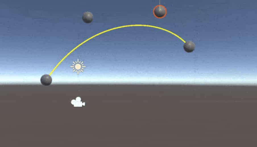
The following script will draw a quadratic Bézier curve using positions p0, p1, and p2. Y'all should create three game objects and assign these objects to corresponding variables in the script to modify the shape of the curve in real-time.
using Organization.Collections; using System.Collections.Generic; using UnityEngine; public class BezierScript : MonoBehaviour { private LineRenderer lineRenderer; public Transform p0; public Transform p1; public Transform p2; void Start( ) { lineRenderer = GetComponent<LineRenderer> ( ) ; } void Update( ) { DrawQuadraticBezierCurve(p0.position, p1.position, p2.position) ; } void DrawQuadraticBezierCurve(Vector3 point0, Vector3 point1, Vector3 point2) { lineRenderer.positionCount = 200 ; bladder t = 0f; Vector3 B = new Vector3( 0 , 0 , 0 ) ; for ( int i = 0 ; i < lineRenderer.positionCount; i+ + ) { B = ( 1 - t) * ( one - t) * point0 + 2 * ( 1 - t) * t * point1 + t * t * point2; lineRenderer.SetPosition(i, B) ; t + = ( 1 / ( float )lineRenderer.positionCount) ; } } }
Likewise, the following method draws a cubic Bézier bend. This time we need iv points.
void DrawCubicBezierCurve(Vector3 point0, Vector3 point1, Vector3 point2, Vector3 point3) { lineRenderer.positionCount = 200 ; float t = 0f; Vector3 B = new Vector3( 0 , 0 , 0 ) ; for ( int i = 0 ; i < lineRenderer.positionCount; i+ + ) { B = ( 1 - t) * ( ane - t) * ( i - t) * point0 + 3 * ( i - t) * ( 1 - t) * t * point1 + 3 * ( i - t) * t * t * point2 + t * t * t * point3; lineRenderer.SetPosition(i, B) ; t + = ( 1 / ( bladder )lineRenderer.positionCount) ; } }
Free Drawing using Line Renderer
In this section, we are going to encounter how we can draw freely using the mouse position. Nosotros tin do this by creating a new game object with a line renderer attached. When we press the left mouse push button, a new game object is created and each frame the position of the mouse added to the line renderer.
First of all, we need a prefab to create a new game object when we press the left mouse push button. This is an empty game object with a line renderer component attached. In add-on to this, do not forget to assign a material to the line renderer component. Create a prefab from this game object.
2d, create an empty game object and attach the following script DrawManager.
using System.Collections; using System.Collections.Generic; using UnityEngine; public class DrawManager: MonoBehaviour { individual LineRenderer lineRenderer; public GameObject drawingPrefab; void Update( ) { if (Input.GetMouseButtonDown( 0 ) ) { GameObject drawing = Instantiate(drawingPrefab) ; lineRenderer = drawing.GetComponent<LineRenderer> ( ) ; } if (Input.GetMouseButton( 0 ) ) { FreeDraw( ) ; } } void FreeDraw( ) { lineRenderer.startWidth = 0.1 f ; lineRenderer.endWidth = 0.1 f ; Vector3 mousePos = new Vector3(Input.mousePosition.ten, Input.mousePosition.y, 10f) ; lineRenderer.positionCount+ + ; lineRenderer.SetPosition(lineRenderer.positionCount - ane , Photographic camera.master.ScreenToWorldPoint(mousePos) ) ; } }
When you press the left mouse button, a new game object is instantiated from the prefab which we created before. We get the line renderer component from this game object. So while we are pressing the left mouse push button, nosotros telephone call FreeDraw() method.
In the FreeDraw method, we take 10 and y components of the mouse position and set the z-position as 10. Here, the mouse position is in the screen space coordinates. But we apply earth space coordinates in line renderer. Therefore we need to convert mouse position to world infinite coordinates. In each frame, we likewise need to increase the number of points. Since we do not know how many points we need, we cannot set up position count before.
References
ane-https://docs.unity3d.com/ScriptReference/LineRenderer.html
ii-http://www.theappguruz.com/weblog/bezier-curve-in-games
iii-https://en.wikipedia.org/wiki/Bézier_curve
4-https://en.wikipedia.org/wiki/Sine_wave
Source: https://www.codinblack.com/how-to-draw-lines-circles-or-anything-else-using-linerenderer/
0 Response to "how to draw slotted spoon in 3d"
Post a Comment